|
|
|
Activity diagrams depict the activities and the results of these activities. UML provides the following definition for these diagrams “a subset of a state transition diagram where the states are activity states and the transitions are automatic” [Schneider & Winters, 1998]. These diagrams stem from Data Flow Diagrams of functional programming. Activity diagrams provide a very natural notation for describing [Detsis, 2000]:
An activity or
action state is an operation that takes
some time to complete or a state of doing something.
For a state with an activity, an outgoing
transition that has no triggering event or guard condition will be fired as soon
as the activity terminates. Such transitions are called automatic or implicit
transitions.
A state
is called an action state when:
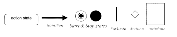
Figure 23 Activity diagram notation
An activity diagram is a variant of a state transition diagram in which most, if not all, the states are action states [Fowler, 2000a]. Activity diagrams support conditional and parallel behaviour.
Branches and merges show conditional behaviour; they are both represented with a diamond (see fig. 23). A branch has a single incoming transition and several, mutually exclusive, guarded outgoing transitions. A merge has multiple input transitions and a single outgoing transition. A merge marks the end of a conditional behaviour started with a branch. Conditional behaviour can also be shown with multiple guarded transitions coming out of and going into an action state, hence no need for branches and merges. Use diamonds if you want to make the branches and merges clear in your diagram.
Parallel behaviour is indicated by forks and joins. A fork
has one incoming transition and several outgoing transitions that occur in
parallel. A join has one outgoing transition and several incoming
transitions and is where a fork is terminated. With a join, the outgoing
transition is taken only when all the states on the incoming transitions have
completed their activities.
An
example activity diagram is shown in the figure below. The figure demonstrates
one fork and one join, with the activities ReadState, ExecuteControlLaws and
OutputDemands occurring in parallel.

Figure 24 An example activity diagram
Dynamic concurrency allows for showing iterations without having constructing a loop. Dynamic concurrency is represented by a (*) inside the action state that is repeated [Fowler, 2000a].
Swimlanes allocate action states to the classes or entities that are responsible for them. To use swimlanes one must arrange the activity diagram into vertical zones separated by lines. Each zone represents the responsibilities of a particular class. “Swinlanes are good in that they combine the activity diagram’s depiction of logic with the interaction diagram’s depiction of responsibility” [Fowler, 2000a:137].
![]()