|
|
|
This is basically the target diagram of the methodology. The diagrams that follow this step are optional and complementary for understanding the problem. The class diagram is updated constantly in every step of the methodology. The class diagrams can be created or updated:
The following stereotypes are commonly used for classes:
o <<boundary>>: for classes that interface the outside world
o <<control>>: for classes that are responsible for the propagation/ manipulation of information
o <<entity>> : for classes that are abstractions of entities of the real world
o <<exception>> : classes that represent an exception
o <<interface>> : a specifier for actions appearing in the outside world
o <<utility>> : utility classes (e.g. a math class)
o <<persistent>> : for persistent classes
Messages of interaction analysis usually become methods of the class that receives the message. An exception to this rule are boundary classes which constitute the graphical part of the system. A message for these classes is a command of the requirements of the GUI [Quatrani, 1998]. These sort of messages are typically implemented as a graphic tool (e.g. a button) and they are not transformed to methods as their behaviour is executed from the graphic tool.
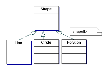
Superclasses with several subclasses may have a name discriminator. The discriminator becomes an attribute of the superclass that identifies the subclass. E.g. in the following figure, shapeID is a name discriminator which has three possible values: Line, Circle or Polygon.

Figure 16 Name discriminator example
The target of the designer is now to refine the class diagram(s) further in order to produce a well-designed system. The following are some guidelines that apply to class diagrams and good design. [Halbert & O’ Brien, 1997] give the following criteria regarding whether some functionality should be placed in an object’s interface or give rise to a new type of object:
Some guidelines/advice are described in the following.
o During analysis, establish associations among classes. These associations exist because of the nature of the classes, not because of their specific implementation.
o For whole/part relationships, specify that a particular association is an aggregation.
o Create generalizations when necessary. During design, inheritance should be used to signify subtypes according to the Liskov Substitution Principle (LSP) [Detsis, 2000]. This strict form of inheritance guarantees correct behaviour of all clients of a class if we substitute the class with any of its subclasses and supports component interchangeability by leveraging polymorphism. Use of inheritance to be avoided are:
o Make an initial estimate of multiplicity in order to expose hidden assumptions
o During design:
The indication of a method might denote a relationship. If the class type that is part of the arguments of the method or that is returned belongs to the basic types of the programming language (e.g. String) then the relationship should not be presented in the class diagram.
Multiplicity of 1 is implemented as an embedded object, a reference, or a pointer. Multiplicity greater than 1 is implemented using a container class (e.g. list, vector) [Quatrani, 1998].
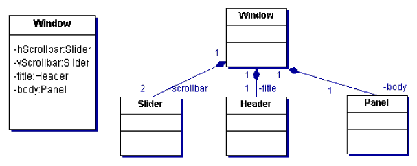
Java does not support aggregation. This is implemented with inner classes. Composition is supported with components as attributes of the containment class (see Figure 17 ).

Figure 17 Composition notation
Java supports simple inheritance plus implementation of interfaces.
A dependency relationship between a client C and a supplier S is implemented either with the supplier class as an argument to the client constructor (i.e. C(S)) or as an attribute to the client class.
The following table shows the map from UML to the Java programming language:
|
Java Element |
UML Element |
|
Package |
Package in the Component View |
|
Import |
· Dependencies between components and packages in the Component View (forward and reverse engineering) · Relationships between classes, which are not located in the same package. In forward engineering, generates a Java import · Dependency relationships for a compilation unit in which an associated class (the client) uses the services of another class (the supplier) if and only if the supplier is defined in a different Java package than the client. |
|
Compilation Unit |
Component (Module Specification) in the Component View |
|
Class |
Class |
|
Interface |
Class with stereotype of “Interface” |
|
Implements Relationship |
Realizes relationship between Java class (subclass) and Java interface (superclass). |
|
Extends Relationship |
· Generalization relationship between Java classes. · Generalization relationship between Java interfaces. |
|
Field |
Attribute or Supplier relationship between classes. · Java instance variables have Static property value set to FALSE. · Java class variables have Static property set to TRUE Association relationships are mapped to fields in a Java class declaration based on the roles the class plays in the association. |
|
Method |
Operation |
|
Class Modifiers |
The final modifier is implemented using the class.Final property. The abstract and public modifiers are part of the class specification. |
|
Field Modifiers {final, transient, volatile} modifiers |
Properties on fields and roles (e.g. Role.Final, Attribute.Volatile, etc.). Static modifier is an element of a role and attribute specification. {attribute.Final, attribute.Transient, attribute.Volatile} |
|
Method modifiers {static, final, abstract, native, synchronized} |
Properties on operations {operation.Static, operation.Final, operation.Abstract, operation.Native, operation.Synchronized} operation properties |
|
{public, protected, private} access |
{public, protected, private} access |
|
package-level access |
implementation access |
|
arrays |
Attributes whose data types contain an array designation (for example, int[ ]). |
|
Static |
Static selector of the attribute or method specification |
Table 1 UML - Java mapping
UML and persistent objects
In this sub-section I give some advice on relating UML to persistent objects (i.e. databases). The material presented here is derived mainly from [Muller, 1999]. I simply describe how UML class notation is implemented in: relational, object-relational and object-oriented DBMSs.
In relational databases, each class becomes a table and each
attribute becomes a column in the table (with public visibility). Relational
databases use stored procedures and functions for the dynamic part.
I recommend to keep the behavioural part in the class instead of transforming
class operations to stored procedures.
“Making a persistent class abstract has no relationship to data in the relational or object-relational database, unlike its effect on transient objects and OO databases. Because of the way you translate the OO data model into the schema, the relational databases do have data for the abstract class. This data represents the part of the concrete objects that comes from the abstract class, not an instance of the abstract class itself.” [Muller, 1999 : 138].
Relational and object-relational databases are not able to represent visibility as they often provide only public attributes, hence no encapsulation [Muller, 1999]. However, as we shall see in our example system, we usually define classes to map relational tables. Hence, it’s a good idea to encapsulate attributes regardless of the way they are stored in the database.
![]()