|
|
|
A domain class diagram contains objects of the real world [Detsis, 2000; Rosenberg, 1999]. A class diagram describes the types of objects in the system and the kinds of relationships that exist among them. UML class diagrams depict the structural view of the system and capture the classes involved and the static relationships between them. [Fowler, 2000a; UML Class Diagrams].
An object is a concept, abstraction, or thing with sharp boundaries and meaning for an application [Rumbaugh et al., 1991]. An object has: state, behaviour and identity. The state of an object is one of the possible contditions in which an object may exist. State is represented by the values or properties or attributes of an object at a given time. The object state changes over time. Behaviour determines how an object reacts, i.e. how its state changes with interaction with other objects. Behaviour is determined by the set of operations or methods the objects can perform. Behaviour may cause a state change. Finally, identity is the nature of an object that distinguishes it from all other objects. It is normally a unique attribute that characterises the object [Detsis, 2000].
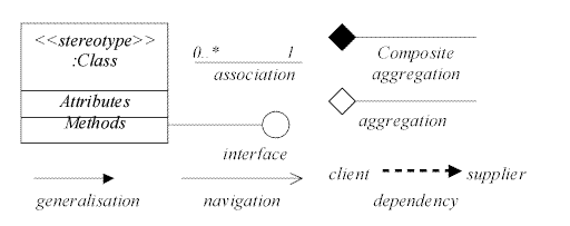
A class diagram consists of the following modelling elements: classes and their structure and behaviour, relationships among classes, multiplicity and navigation indicators and role names.
A class is a set of objects that share a common structure (represented by attributes), a common behaviour (represented by operations) common relationships and common semantics. In other words, a class is a template for creating objects. Every object is an instance of a class. Classes are usually static while objects are dynamic (they can be created and destroyed during program execution).
stereotype visibility name : type-expression = initial-value { property-string }
stereotype visibility name (parameter-list): return-type-expression { property-string }

Figure 8 Components of a class diagram
The next figure shows an example association relationship. The relationship is named with the name employs. On the bottom of the relationship we see the multiplicity (cardinality) of the relationship. A company employs many persons. A person is employed in one company. As we see, a relationship is read from left to right. The relationship also contains role names. The company, as the employer, employs many persons. A person, is employed, as an employee, by one company.

Figure 9 Example association relationship
An association class is a relationship that has structure and behaviour. This happens when the information refers to the link between two objects and not to one of the objects. An example is shown in Figure 10. A student may choose up to 10 courses and 3 to 15 students can participate in each course. Grade class does not belong to the Student class as a student may have different grades for each course. Grade class does not belong to the Course class either, as a course may have different grades for each student. Hence, it belongs to their link.

Figure 10 Example of an association class
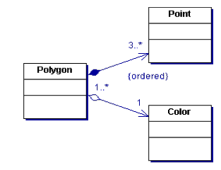
The next figure shows an example of an aggregation and a composition. An instance of Polygon consists of 3 or more instances of Point. Composition means that a Point can exist only inside one Polygon only and that when the polygon is deleted all its points will be deleted as well. Multiplicity of one in the composition on the side of the Polygon is implied (a specific instance of a Point cannot exist in another instance of Polygon at a specific time). The aggregation, however, means that a Color may be shared by many polygons.

Figure 11 Aggregation and Composition example
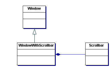
The next figure shows an example of a generalisation and aggregation relationships. A WindowWithScrollbar is a Window but is not a Scrollbar. A Scrollbar is a part of a WindowWithScrollbar. Finally, this is a composite aggregation as a scrollbar can not stand on its own in an application.

Figure 12 A Window with a scrollbar
![]()