|
|
|
The use case view of the system consists of use case diagrams. A use case diagram shows the relationships among actors and use cases within the system. A use case diagram consists of actors, use cases and relationships between them.
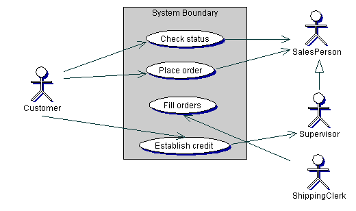
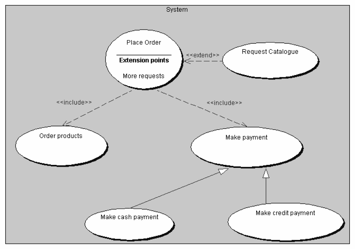
In Figure 4, we can see the components of a use case diagram. Figure 5 displays an example use case diagram that shows how the components are used. Figure 6 shows use case relationships as of UML 1.3.

Figure 4 Components of a use
case diagram
The primary purposes of the use case model is [Eriksson & Penker, 1998]:
The actor depicts the role of a user
or users with respect to the system who
exist outside of the system but interact
with it. An actor might be a user,
a database or another system that communicates
with our system via a communications
link. The sum of actors depicts everything
that needs to exchange information
with our system. Actors are identified
as adjectives or nouns in the short
description of the system. Examples of
actors are shown in Figure 5.

Figure 5 A use case diagram
A use case is a sequence
of actions that the actor executes in
a system to accomplish a task. A use
case is described, from the user point
of view, as a verbal sentence in present
tense in active voice. A correct and
complete use case describes a part of
the use of the system without assuming
anything about its design or implementation.
The result is that all the functionality
of the system will be described by
use cases. According to [Fowler, 2000a],
a use case describes a main functionality
of the system, which is complete from
beginning to end. A use case should
deliver something useful to its actor.
A use case consists of a number of statements
expressed in a natural language.
The statements are time-ordered (i.e.
they appear in the order things happen
in the system) and simple and declarative
(i.e. they do not include alternatives
or IF-THEN-ELSE constructs).
To create use cases we focus in the various
scenarios. During this step it
would be desirable for the manual of
the system to be produced. Thus, the
various scenarios would correspond to
the manuals' chapters.
In every use case we describe scenarios
in a basic as well as alternative
action flows. Each use case is described
with the following piece of information:

Figure 6 Use case relationships
The <<include>> relationship
(see fig. 4) refers to a use case that
makes a complete use of another use
case. This normally happens when we find
ourselves to use the same text in
many parts of our diagram. We can then
move this text in a new use case and
update our diagram with an <<include>>
relationship. The use
case that includes the new use case is
not complete by itself anymore, but
the new use case is complete and it does
not know that it is being used elsewhere.
The <<extend>> relationship is used when we have an alternative flow that we wish to include in the use case. It is used when we wish to demonstrate alternative behaviour, i.e. behaviour that is executed only under certain conditions. A use case that contains extension points is shown in Figure 6. Every extension point should have a unique name. An <<extend>> relationship is used to show:
In the use case documentation there should be stated what happens in the extension points. The extension consists of a condition, which once satisfied, the steps of the use case description that relate to the extension point are executed.