Would you like to make this site your homepage? It's fast and easy...
Yes, Please make this my home page!
1.
What is UML
Unified Modelling Language (UML) is a language for specifying, constructing, visualizing, and documenting the artifacts of a software system. It consists of modeling elements, i.e. abstractions drawn from the system being modeled.
UML consists of 7 diagrams which we shall describe in the rest of this book, namely: use case diagrams, class and object diagrams, collaboration diagrams, sequence diagrams, state transition diagrams, activity diagrams and component and deployment diagrams. The diagrams are the actual graphs that show model element symbols arranged to illustrate a particular part or aspect of the system.
UML
consists of the following four views of
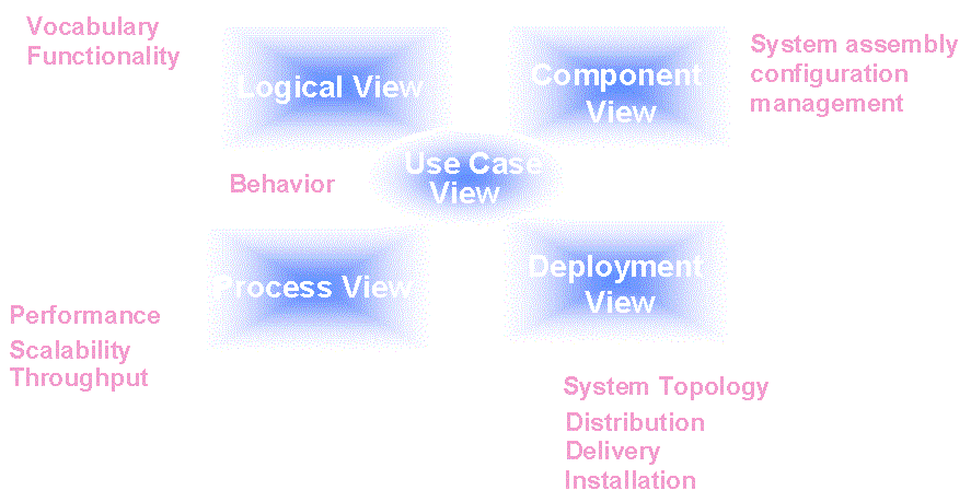
the system under development (see Fig.
3) [Eriksson & Penker, 1998; Kruchten, 2000]:
- Use case view: shows the functionality of the system as perceived by external actors; it is described in use case diagrams and occasionally in activity diagrams.
- Logical view: shows how this functionality is designed inside the system, in terms of the systemís static structure and dynamic behaviour; it is described in class and object diagrams (static model) and state transition, sequence, collaboration and activity diagrams (dynamic model)
- Component view: shows the organisation of the software components; it is described in component diagrams.
- Deployment view: shows the physical configuration (deployment) of run-time processing nodes within computers and devices and the components, processes, and objects that live on them; it is described in deployment diagrams.
- Process view: shows the concurrent aspect of the system at runtime, like tasks, threads, processes and interactions and addresses problems with communication and synchronisation of these threads; it is described in dynamic diagrams (state transition, sequence, collaboration and activity diagrams) and implementation diagrams (component and deployment diagrams).

Figure 3
The 4+1 View Model
of Architecture
Each
system consists of the static and the dynamic model. The
static model is depicted in the class and
object diagrams.
However, it reveals little
concerning system behaviour. System behavior
is captured graphically using
scenarios (i.e. use case diagrams), collaboration
diagrams, sequence diagrams,
state transition and activity diagrams. These
consist the dynamic model
of the system. System behaviour is the total
behaviour of all objects belonging
to the system.
If
we want to map the above five views to the
iterative life cycle phases
of fig. 3, we could say the following:
-
Object Oriented Analysis (OOA), which develops a model of users' requirements from the user's perspective, maps to the Use case view.
-
Object Oriented Design (OOD) adds details and design decisions (from the developer's perspective) to the analysis and maps to the logical view.
-
Finally, Implementation or Object Oriented Programming (OOP) maps to the process, deployment and component view.
However,
it should be mentioned that this mapping
is not as strict
as it appears above.


